
Hall Sensor

The Hall effect is the working principle of the Hall sensor. It is a kind of electromagnetic effect, in which an orthogonal current and magnetic field are applied to the Semiconductor. The carriers in the Semiconductor are subjected to the Lorentz force and deflected. In different directions Gathering, thereby generating an electric field. There is a built-in voltage, this voltage is the Hall voltage, the greater the magnetic field strength, the greater the Hall voltage.
Hall Sensor
Hall sensor

The working principle of the linear Hall sensor, the output of the linear Hall sensor is an electrical signal proportional to the measured magnetic field strength. For example, the linear Hall sensor 3503 has three pins which are positive VS, V out and GND. Among them The positive VS is connected to a power supply of 4.5 to 6V. Power is supplied to the 3503, and the GND is grounded. The shell of the 3503 can induce the magnetic field, and implements the magnetic field strength in the form of voltage output at the pin of V out. The next output diagram shows that the 3503 is good When the magnetic field strength is 0 Gauss, V out is equal to 2.5V. When the magnetic field strength changes by 1 Gauss, the output changes about 1.3 millivolts.
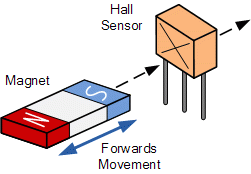
When the 3503 sensor measures the magnetic field, it needs to pass the magnetic field lines through its effective sensing element to be detected. The magnetic field lines pass through the Hall sensor. The stronger the magnetic field, the more magnetic field lines pass through the Hall sensor, and the weaker the magnetic field passes through. The fewer lines of magnetic force, the Hall sensor outputs a corresponding signal to indicate the strength of the magnetic field according to the number of magnetic lines that pass through.

Comments

Popular posts from this blog

IXYS DSS2X160-01A

# DSS2X160-01A IXYS DSS2X160-01A New Rectifier Diode Schottky 1 Phase 2 Element 160A 100V V(RRM) Silicon MINI BLOC SOT-227 2 PIN, DSS2X160-01A pictures, DSS2X160-01A price, #DSS2X160-01A supplier ------------------------------------------------------------------- Email: sales@shunlongwei.com https://www.slw-ele.com/dss2x160-01a.html ------------------------------------------------------------------- Manufacturer Part Number: DSS2X160-01A Pbfree Code: Yes Part Life Cycle Code: Active Ihs Manufacturer: IXYS CORP Part Package Code: SOT-227 Package Description: R-XUFM-N2 Pin Count: 4 ECCN Code: EAR99 HTS Code: 8541.10.00.80 Manufacturer: IXYS Corporation Additional Feature: FREE WHEELING DIODE Application: GENERAL PURPOSE Case Connection: CATHODE Configuration: COMMON CATHODE, 2 ELEMENTS Diode Element Material: SILICON Diode Type: ...

Advantages of five-axis machining of aluminum alloy parts

Aluminum alloy is a very good material for parts. Its low density can achieve lightweight parts and its strength is very high even comparable to steel. In addition, its corrosion resistance, electrical conductivity and thermal conductivity are very good. But there is a major defect that precision machining is very difficult, but the emergence of five-axis machining technology has solved this problem well. Today, let’s take a look at the advantages of five-axis machining of this aluminum alloy part. 1. Reduce processing time Table of Contents 1. Reduce processing time 2. Improve processing accuracy 3. High production efficiency In the processing, the flat-bottomed end mill is used to maintain the vertical surface of the complex mold processing surface, which can greatly reduce the processing time. It is also suitable for side milling with angled surfaces, which can eliminate the rib-like shape caused by the spherical end mill processing. The texture...

Elimination of Gear Backlash in CNC Machining Feed System

Elimination of Gear Backlash in CNC Machining Feed System   The transmission gear in the feed system of the CNC machining machine tool must eliminate the transmission gap between the meshing gears as much as possible, otherwise the motion will lag behind the command signal after each reversal of the feed system, which will affect the machining accuracy (accuracy) ). There are the following two common methods for CNC machining machine tools to eliminate the transmission gear gap.   1. Rigidity adjustment method   The rigid adjustment method is an adjustment method that cannot be automatically compensated for the tooth side clearance after adjustment. Therefore, the pitch tolerance and tooth thickness of the gear must be strictly controlled, otherwise the flexibility of the transmission will be affected. This adjustment method has a relatively simple structure and a better transmission rigidity.   (1) Eccentric shaft adjustment method   As shown in Figure 610, the...